Rigid body elements
RBE2 and RBE3
Daniel Weschke
November 11, 2014
Finite element software often have rigid body elements (RBE), for example to apply loads or assemble bodies.
RBE3 have the same name in APDL but RBE2 are called CERIG in APDL. The corresponding menu path are:
Main Menu > Preprocesser > Coupling / Ceqn > Rigid Region
Main Menu > Preprocesser > Coupling / Ceqn > Dist F/M at Mstr
Both element types are only useful in the linear analysis and require a further master element, if not two bodies are to be connected. Usually a zero mass point element MASS21 is used as a master node.
Main Menu > Preprocesser > Element Type > Add/Edit/Delete > Add… > Structural Mass > 3D Mass 21
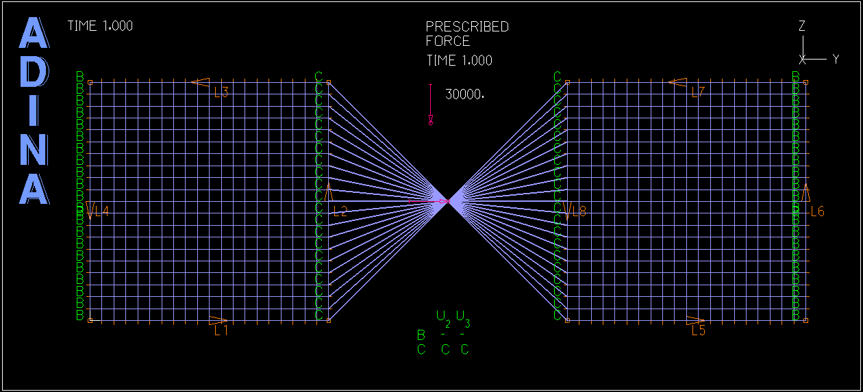
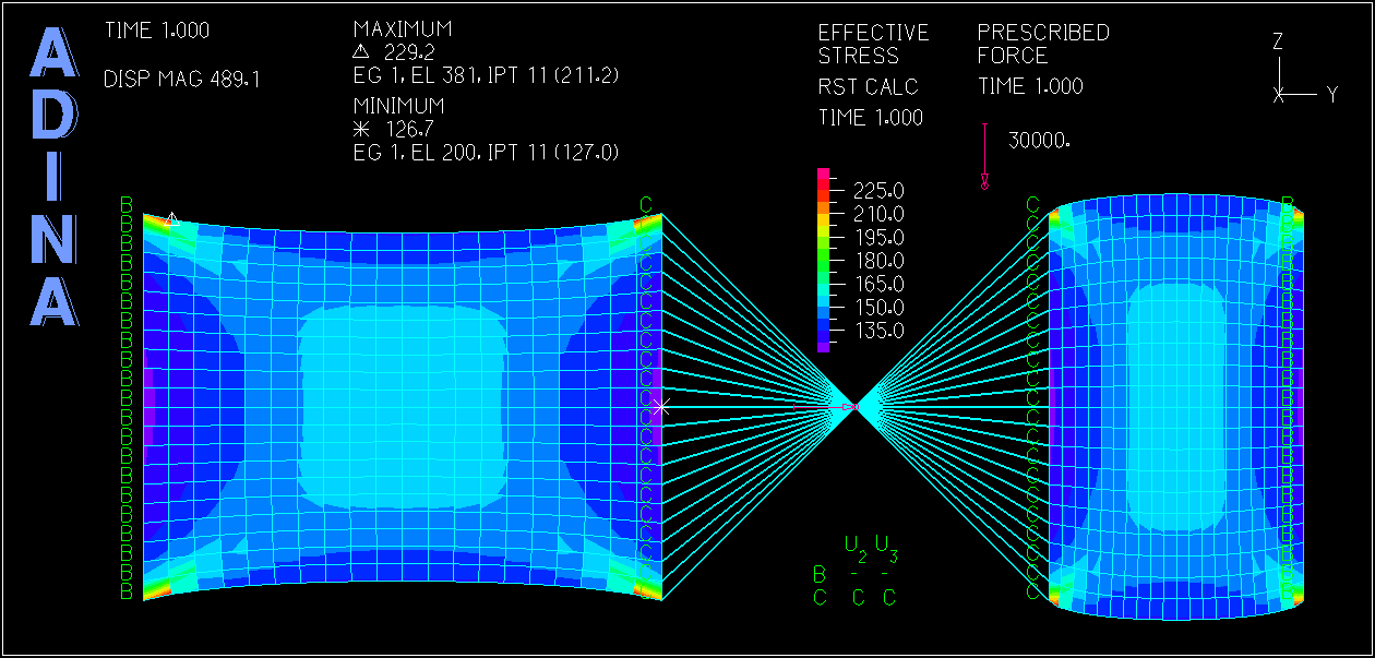
Two MAPDL input files demonstrating the usage: Plane structure with RBE2 and RBE3
/BATCH,LIST
FINISH
/CLEAR
/TITLE, RBE2
/FILNAM,file

/PREP7
! Elements
ET,1,PLANE182
ET,2,MASS21

! Real Contants
R,1,0,0,0,0,0,0,

! Material Props
MP,EX,1,2.1e5
MP,PRXY,1,.3

! Sections
SECT,1,SHELL,,
SECDATA,1,1,0.0,3

! Modeling
K,1,150,50,
RECTNG,0,100,0,100,
RECTNG,200,300,0,100,

! Meshing
AESIZE,ALL,5,
AMESH,ALL

TYPE,2
KMESH,1

! Coupling / Ceqn
masternode = NODE(150,50,0)
NSEL,S,NODE,,masternode

LSEL,S,LINE,,2   ! slavenodes
LSEL,A,LINE,,8
NSLL,A,1

CERIG,masternode,ALL,ALL,,,,
! RBE3,masternode,ALL,ALL,,
! nonlinear -> MPC184
ALLSEL

! Loads
DL,4,,ALL
DL,6,,ALL
FK,1,FX,30000


/SOL
ANTYPE,0
/STATUS,SOLU
SOLVE


/POST1
/EFACET,1
PLNSOL,S,EQV, 0,1.0

FINISH
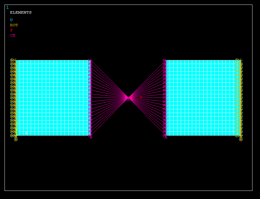
Boundaries
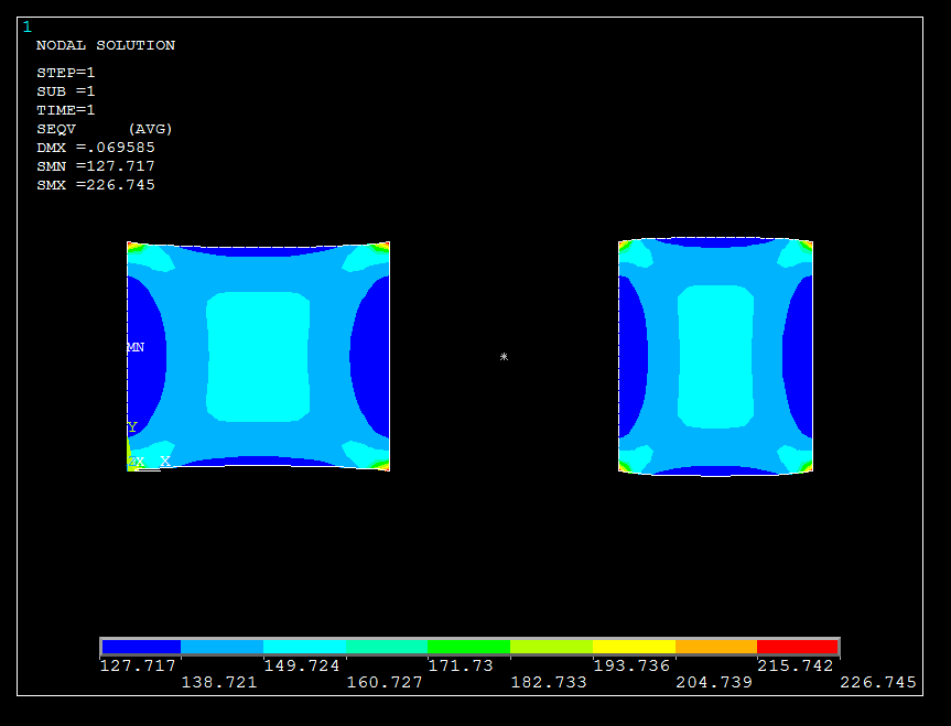
Stress field
or Shell structure with RBE2 and RBE3
/BATCH,LIST
FINISH
/CLEAR
/TITLE, RBE2
/FILNAM,file

/PREP7
! Elements
ET,1,SHELL181
ET,2,MASS21

! Real Contants
R,1,0,0,0,0,0,0,

! Material Props
MP,EX,1,0.7e5
MP,PRXY,1,.3

! Sections
SECT,1,SHELL,,
SECDATA,1,1,0.0,3

! Modeling
K,1,,,
K,2,50,20,
K,3,100,,
K,4,,,50
K,5,50,50,25

LARC,1,3,2
L,1,4

ADRAG,1,,,,,,2

! Meshing
AESIZE,ALL,1,
AMESH,ALL

TYPE,2
KMESH,5

! Coupling / Ceqn
masternode = NODE(50,50,25)
NSEL,S,NODE,,masternode

NSEL,S,LOC,X,40,60   ! slavenodes
NSEL,R,LOC,Z,20,30

CERIG,masternode,ALL,ALL,,,,
!RBE3,masternode,ALL,ALL,,
! nonlinear -> MPC184

ALLSEL

! Loads
LSEL,R,LOC,Z,25
DL,ALL,,ALL
FK,5,FY,-500

EPLOT
/VIEW,1,1,2,3
/PBC,ALL,,1
/REP

/SOL
ANTYPE,0
/STATUS,SOLU
SOLVE

/POST1
/EFACET,1
PLNSOL,S,EQV,0,1.0

FINISH
For non-linear analysis, however, there is the MPC184 (Multipoint Constraint Element). These type of elements can be found under:
Main Menu > Preprocesser > Element Type > Add/Edit/Delete > Add… > Constraint > Nonlinear MPC 184
If not two bodies are to be connected a further master node is required.
Main Menu > Preprocesser > Modeling > Create > Nodes > In Active CS
Last step is to create the MPC elements
Main Menu > Preprocesser > Modeling > Create > Elements > Auto Numbered > Thru Nodes
In the workbench of ANSYS, the RBE2 and RBE3, using the example of Mechanical, are shown by the Static Structural analysis. These elements can be found by inserting the menu point Remote Points over the Model in the Outline (structure tree).
Outline > Model > Context menu > Insert > Remote Point
The Remote Points entry is then also displayed in the Outline. The real master element (Remote Point) and thus the RBE2 or RBE3 can then be inserted via this entry.
Outline > Remote Points > Context menu > Insert > Remote Point
If an remote point is inserted, the slave area can be defined in the Details window, with the first two fields in the sub-point area. For example, use the Scoping Method: Geometry Selection and then select in the geometry corresponding geometric elements such as lines. The master node is defined with the subsequent coordinates. Finally, the Behavior can be set to either Rigid - for RBE2 - or Deformable - for RBE3.
Details of Remote Point:
Scoping Method > Geometry Selection (as an example)
Geometry Selection > Select the desired geometry elements of a type from the geometry window (slave region)
X- / Y- / Z-coordinate > 0 / 0 / 0 (Master Point)
Behavior > Rigid (RBE2) or Deformable (RBE3)
To visualize the elements select the Remote Points in the Outline and change the property Show Connection Lines in the details view.
Details of Remote Points > Show Connection Lines > Yes
Linked boundary conditions can then be, for example, the external force, the moment, or the external displacement. It is then to be selected as the Scoping Method: External point.
In ADINA Structures there are the “RBE2” under the name Rigid Links.
You can find them under:
Model > Constraints > Rigid Links...
or as command
RIGIDLINK 1 NODESET 2 NODESET 1
or longer command but explanatory version
RIGIDLINK NAME=1 SLAVETYP=NODESET SLAVENAM=2 MASTERTY=NODESET MASTERNA=1
With RBE3, on the other hand, the load must be expressed by a statically equivalent line or surface load, since these elements are not available here.