Cross-section and derived sizes
Properties of a Plane Area
Daniel Weschke
November 16, 2014
1 Parameters
\(A\) Cross-section
\(I_{ij}\) Moment of inertia of plane area or second moment of area. If \(i=j\) then one speaks of moments of inertia, then often only \(I_i\). If \(i\ne{}j\) then one speaks of product of inertia
\(I_T\) Torsion constant for the section or torsional moment of inertia or torsional resistance
\(I_\omega\) \((C_W)\) Warping constant
\(y_S\), \(z_S\) \((r_S)\) Coordinates to the geometric center of a plane figure, centroid (possibly other spatial directions). Usually set as a reference.
\(y_M\), \(z_M\) \((r_M)\) Coordinates to the shear center (also known as the elastic axis or torsional axis) (possibly other spatial directions). Usually with reference to the reference point, the centroid.
\(\kappa_{ij}\) Shear correction factor
Indices \(i,j\) represent the spatial directions \(x,y,z\).
2 Rectangular cross-section
Given a rectangular cross-section with the edge lengths \(b\) of 10 mm and \(h\) of 20 mm. The cross-section normal, possibly also the beam axis, is collinear with the x axis. For the cross-section, the following values can be derived:
The Area \(A\)
The moments of inertia \(I_{yy}\), \(I_{zz}\) and the product of inertia \(I_{yz}\)
The product of inertia \(I_{yz}\) shows that this becomes zero as soon as there is a symmetry axis.
The torsion constant \(I_T\)
Herein the torsion function \(\Phi\) and the constant \(\phi\) for rectangular cross sections or rectangle regions are obtained from double Fourier series. The factor 0.686045 applies to rectangular cross sections with a side ratio \(h/b=2\).
The warping constant \(I_\omega\)
The warp function \(U\) is derived from the relation with the torsion function \(\Phi\), which is derived from the calculation of the torsional inertial moment \(I_T\). The factor 1.34199 applies to rectangular cross sections with an aspect ratio \(h/b=2\).
The coordinates to the centroid \(y_S\) and \(z_S\) as well as the coordinates to the shear center \(y_M\) and \(z_M\)
Both points lie one on top of the other, since the double-symmetrical profile. This also applies to point-symmetrical profiles.
The shear correction factors \(\kappa_{yy}\), \(\kappa_{zz}\) and \(\kappa_{yz}\)
Here, \(A_s\) is the shear area. The shear correction factor \(\kappa_{yz}\) is zero analogous to the product of inertia \(I_{yz}\).
Rectangular cross-section with ANSYS Mechanical APDL for beams can be created and displayed using the following menu path:
Main Menu > Preprocesser > Sections > Beam > Common Sections
Main Menu > Preprocessor > Sections > Beam > Plot Section
MAPDL-Snippet:
/PREP7
! Sections
SECT,1,BEAM,RECT
SECDATA,10,20
SECPLOT,1,0
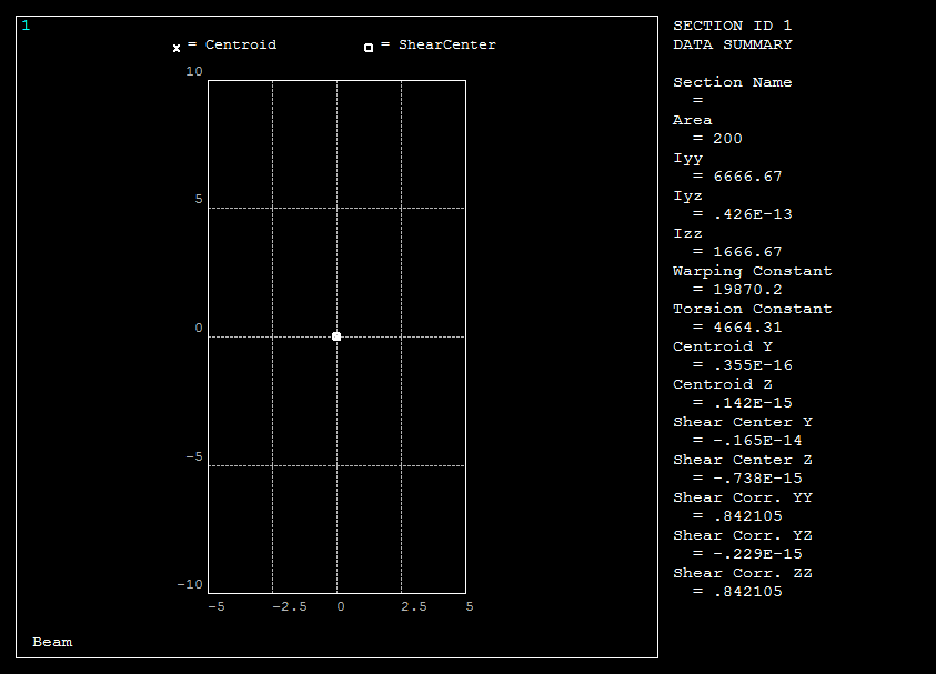
Meaning:
Area \(\rightarrow A\)
Iyy \(\rightarrow I_{yy}\)
Iyz \(\rightarrow I_{yz}\)
Izz \(\rightarrow I_{zz}\)
Warping Constant \(\rightarrow I_\omega\)
Torsion Constant \(\rightarrow I_T\)
Centroid Y \(\rightarrow y_S\)
Centroid Z \(\rightarrow z_S\)
Shear Center Y \(\rightarrow y_M\)
Shear Center Z \(\rightarrow z_M\)
Shear Corr. YY \(\rightarrow \kappa_{yy}\)
Shear Corr. YZ \(\rightarrow \kappa_{yz}\)
Shear Corr. ZZ \(\rightarrow \kappa_{zz}\)
The large deviation of the warping constant can be explained by the fact that the built-in calculation rule has its validity in narrow cross-sections. For example, with an edge length of 10 mm and 200 mm, the analytical warping constant is \(5.606\cdot10^7\mathrm{mm^6}\) and that of ANSYS is \(5.49\cdot10^7\mathrm{mm^6}\).
Rectangular cross-section with ANSYS Workbench
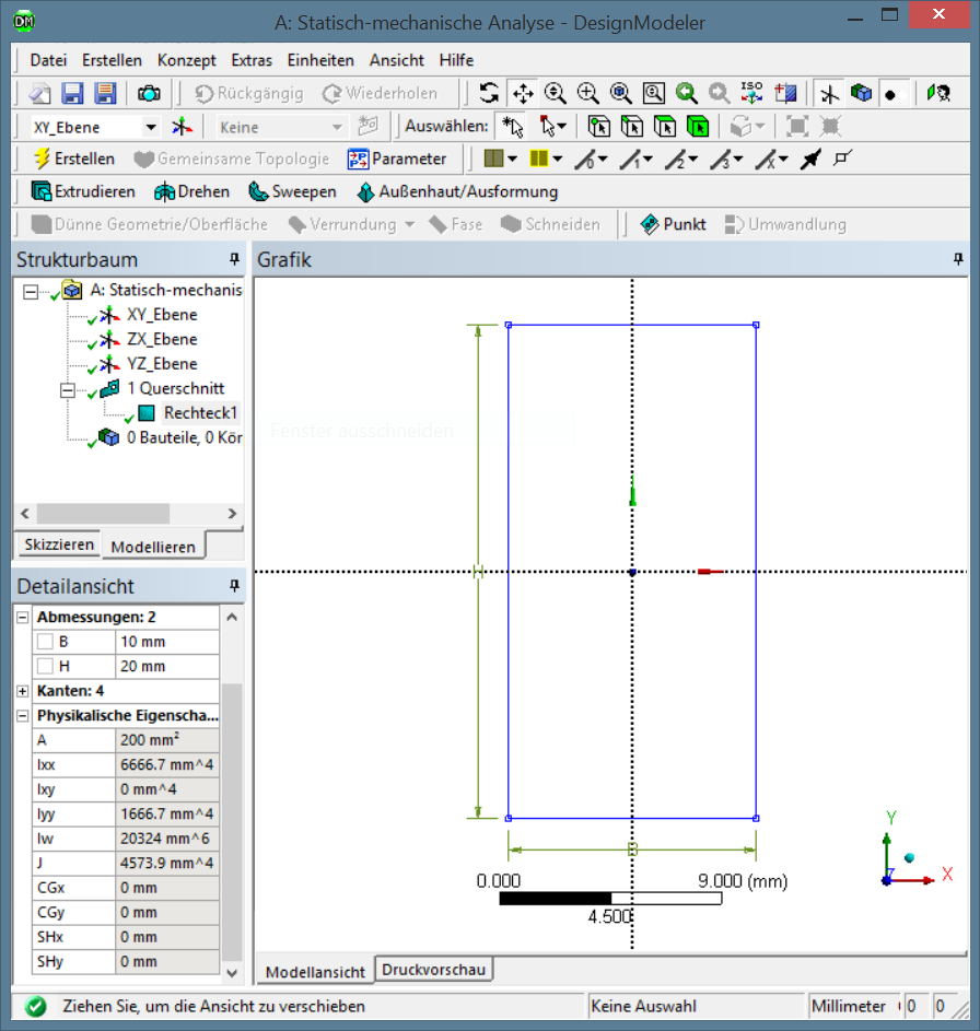
In the DesignModeler, cross-sections can be added via
Menu > Concept > Cross Section > Rectangular
Meaning:
A \(\rightarrow A\)
Ixx \(\rightarrow I_{yy}\)
Ixy \(\rightarrow I_{yz}\)
Iyy \(\rightarrow I_{zz}\)
Iw \(\rightarrow I_\omega\)
J \(\rightarrow I_T\)
CGx \(\rightarrow y_S\)
CGy \(\rightarrow z_S\)
SHx \(\rightarrow y_M\)
SHy \(\rightarrow z_M\)
The large deviation of the warping constant can be explained by the fact that the built-in calculation rule has its validity in narrow cross-sections. For example, with an edge length of 10 mm and 200 mm, the analytical warping constant is \(5.6059\cdot10^7\mathrm{mm^6}\) and that of ANSYS is \(5.5022\cdot10^7\mathrm{mm^6}\).
In ADINA Structures, rectangular cross-sections can be added via
Menu > Model > Cross-Sections...
or as command
CROSS-SECTION RECTANGULAR 1 10 20
or longer command but explanatory version
CROSS-SECTION RECTANGULAR NAME=1 WIDTH=10 HEIGHT=20
All necessary values must be entered.